Goal: Put all your skills together to build a robot with two light sensors that control two motors, gearboxes and wheels.
Materials:
- Arduino Microcontroller,
- 2x photoresistors & 150k resistors,
- 2x transistors
- jumpers,
- 2x motor & gearbox sets
(To learn more visit www.ZombiebotHQ.com/components )
Overview: This is where it all comes together: we’re controlling motors and gearboxes with our light sensors so that our robot can begin to think and move for itself.
Instructions:
- Make a second light sensor (like the one in Challenge Three). These two sensor will be our robot’s ‘eyes’. Wrap some tape around the photoresistor’s legs to prevent the wires from touching (Fig. 1).

Fig. 1
- Connect both transistors to the Green, Blue and Black M/F jumpers exactly like they are shown below. Looking down on the transistor, the correct colour order is (L-R) green, blue, black. Transistors allow us to control a larger voltage (9v) with a smaller voltage (5v from our Arduino). We’ll use this to control our motors.

Fig. 2
- Video instructions:
Or follow these instructions to set up your breadboard. Step-by-step: connect the colours up: The black jumpers from the transistors & light sensors go into the black power rail (with the black barrel jack jumper and the black 9v power leads). The red jumpers from the motors go into the red power rail. The blue jumpers from the Transistors clip into the blue leads from the motors. Use a yellow M-M jumper to join the Arduino 5v pin to the yellow terminal strip on the breadboard, then connect the yellow jumpers from the light sensors into the same yellow terminal strip. The green jumpers from the light sensors go into the A0 and A1 pins on the Arduino. The green jumpers from the transistors go into the Digital 3 and 5 pins on the Arduino. We’re ready to roll!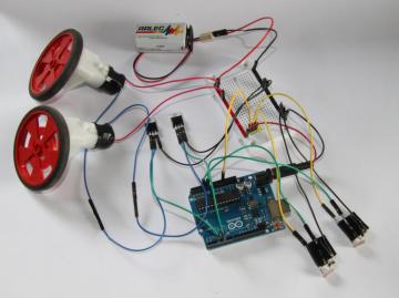
Fig.3
- Download this sketch: Zombiebots_Challenge Five v2, open it and upload it to your Arduino.


You will use these skills later by: Saving humankind from Zombies!
