Goal:
Build a night time alarm to sound when night falls
Materials:
- 1x Arduino Microcontroller,
- 1x Piezo buzzer,
- 1x photoresistor,
- 1x 150kΩ resistor,
- Jumper wires,
(To learn more visit www.ZombiebotHQ.com/components)
Overview:
This challenge adds some braaaains to our electronics, in the form of an Arduino microcontroller. A microcontroller receives input from the environment around it (from light sensors, temperature sensors, switches etc.) then perform actions based on these inputs. Using this combination of input & output we can do just about anything we like.
Instructions:
For complete visual instructions, click here. (Also: ‘Blink‘ and the Light Sensor.)
- Download, install and set up the www.arduino.cc software.
Stage One: Make the Light Blink
- Look closely at the Arduino. Can you see each pin has a label like D1, D2, D3 etc.? And remember the letters and numbers on your breadboard? Push your Arduino onto the breadboard so pin D13 is in slot H30, and D12 is in D30 and so on. It should look like the one in Fig. 1 below.
-
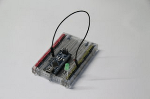
Fig. 1 – Click the image to see detailed instructions.
An Arduino program is called a sketch, and one of the simplest sketches is called ‘Blink’. Put an L.E.D. onto your breadboard with the long leg in J30 and the short leg into the black power rail nearby. We’re going to use the Arduino to turn this L.E.D. on and off. In order to complete the circuit (circle) we need to join the black power rail back to the Arduino. Using a black jumper and to connect the black power rail to A19 (Fig. 1). This is the Arduino GND pin – also known as (-).
- In the Arduino software, select the correct Arduino board by going Tools > Board > Arduino Nano w/ ATmega328. Now open the Blink sketch by going File > Examples > 01. Basics > Blink. You can send it to the Arduino by connecting your computer to the Arduino using the USB cable then selecting File > Upload. If your L.E.D. blinks off and on, congratulations, you’ve programmed your first Arduino! Now- find where the program turns the L.E.D. on for 1000 milliseconds, then turns it off for 1000 milliseconds. Have a play around with these numbers and re-upload your sketch to see if you can speed up the blinking. We’re playing with code!
Stage Two: Create a Night-time Alarm:
-
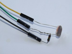
Fig. 2 – Click the image to see detailed instructions.
Time to get serious! Let’s build a light sensor like the one below using the photoresistor, the 150KΩ resistor and three M/F jumpers (yellow, green and black- the colours are important). Carefully twist one of the resistor legs around one of the photoresistor legs (be careful not to wiggle the legs too much because they do get weak and break). Now add M-F jumpers, matching the colours to the photograph below.
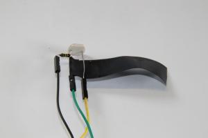
Fig. 3 – When you have made your light sensor, wrap some tape around the legs so none of them can touch each other.
-
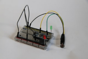
Fig. 4 – Click the image for detailed instructions
Now let’s put it all together and use our light sensor to tell the Arduino how much light there is in the room. If the light levels drop too low, we’ll turn a red L.E.D. and a buzzer alarm on.We’ve written a couple of sketches that we can use with your light sensor. Download and unzip this file: Zombiebot_Challenge_Three. Once you have unzipped the two sketches, open the one called ‘Zombiebot Night Time Alarm v2‘ with the Arduino software. If you have put all of the wires in the right places and set your breadboard up properly, the green L.E.D. should light up. Cover the light sensor with your hand to amke the red L.E.D. light up and the piezo sound. You’ve made an alarm with will activate when the light in the room drops below a certain point!
- Extra fun: once you have successfully built your night time alarm, open the second sketch (‘Zombiebots Play A Tune v1‘ and upload it to your Arduino. Can you recognise the tune? When you have worked it out, re-upload the first sketch to return yout setup to being a night-time alarm.
You will use these skills later by:
- We will eventually use two photoresistors for our robot. They will act like eyes so that when the robot senses it is heading into a corner, it will adjust direction.
